Skip to Main Content

EMX IRB-MON2 Universal Thru-Beam Photoeye Kit

Brand:
Mfr. Model #:
IRB-MON2
KR Part #:
EMIRB-MON2
Weight:
0.00 lbs
Out of Stock - Pre-Order Now
MSRP
$270.10
Now Only!
$175.39

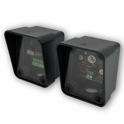
A universal thru beam infrared photoeye kit from EMX industries. Works as an external entrapment protection device non-contact sensor for use with automatic gates and doors. The photoeye provides a signal to the gate or door operator that the beam is, or is not obstructed. It's able to operate up to 155 feet.

Product Description

Universal Thru Beam Photoeye Kit

This thru beam photoeye is an external entrapment protection non-contact sensor used with automatic gates and doors. The device is able to operate up to 115 feet and is compatible with a wide range of input voltages. The photoeye provides a signal to the gate or door operator that the beam is, or is not obstructed.

A helpful receiver green alignment indicator provides status information, making set-up and alignment much simpler. The part is generally compatible with operators that accommodate monitored external entrapment devices.

Specifications:

  • Operating Range: 5 to 155 ft.
  • Max Voltage AC: 24
  • Max Voltage DC: 35
  • Min Temp: -40 F
  • Max Temp: 170 F
  • Conduit Hole Size: 1/2" NPT
  • B1 type
  • Supported Monitoring Methods: 10K, 2-wire pulse, normally closed
  • Connections: “Removeable” screw terminal for easy wiring

Monitoring Methods:

  • Normally Closed
  • 10k Resistive Termination
  • Two-Wire Pulse, 2 Frequency
  • Two-Wire Pulse, 3 Frequency

Installation:

  1. Set Dipswitch for Monitoring Method- Check gate or door opening operator manual to determine which monitoring method is necessary for your operator. Remove the front cover. Set IRB-MON2 dipswitches for needed operator monitoring method.
  2. Mounting: Determine mounting height from 4 to 25 inches above the ground. Mount housings uses 4 screws that go through the inside of the housing, inside of the 4 holes in the corners.
  3. Wiring: Connect 6-35 VDC or 12-24 VAC to the “Power Input” terminals on the transmitter and receiver. Remove green screw terminals for ease of wiring.
  4. Optional: Install optional sunshield over the receiver reflector to reduce the effects of sun interference or crosstalk.
  5. Power: Apply power to the IRB-MON2 transmitter and receiver.
  6. Aligned Correctly: The receiver and transmitter are aligned when the RECEIVER green LED is on “solid”. Once on solid, then slowly decrease the sensitivity setting on the receiver until the receiver green LED just starts to flash. Now, increase sensitivity setting “one quarter” turn clockwise. Confirm receiver LED is still on solid.
  7. Test Obstruction: Place an obstruction (ex. hand) between the transmitter and receiver – the receiver green LED should start flashing. Check the operator control board and verify the safety input is recognized by the operator. Test the beam with an obstruction between the transmitter and receiver at multiple distances to confirm proper operation.
  8. Remove Obstruction: Remove the obstruction and the receiver green LED will turn on solid.
  9. Secure the Covers: Secure the covers using all four plastic screws provided.Check the(or call the operator company)yours (remove 4 plastic screws in each unit), and thenMON2neededOPERATORo determine whichRemove the frontet IRBfor
Updating...
Loading...